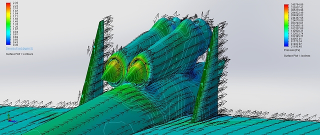

- #CFD SOLIDWORKS FLOW SIMULATION MANUAL#
- #CFD SOLIDWORKS FLOW SIMULATION SOFTWARE#
- #CFD SOLIDWORKS FLOW SIMULATION SERIES#
SOLIDWORKS Flow Simulation offers two flow modules that encompass industry specific tools, practices and simulation methodologies a. CFD analysis of a internal flow for a fluid through a U-tube will be analyzed using solidworks cfd simulations module.Velocity, and temperature contours will. Since we don’t know flow characteristics until enough iterations are solved for the flow to have developed, this takes place during the calculation stage.Įach stage has its own settings. SOLIDWORKS Flow Simulation takes the complexity out of computational fluid dynamics (CFD) enabling engineers and designers to use CFD insights to make technical decisions in a concurrent engineering approach.

Understanding these performance indicators with the use of CFD simulation enables engineers to explore more ideas and make better decisions.
#CFD SOLIDWORKS FLOW SIMULATION SOFTWARE#
This is when the software refines the mesh based on the flow characteristics taking place in order to accurately capture the flow. Predicting fluid flow rates, pressure drops, and turbulence are just a few items that are challenging to measure during design. Areas of curvature, thin walls, and narrow channels all play into how much the cells get refined.

The initial mesh takes software defaults or user input settings related to model geometry and refines the basic mesh around the model geometry. This is a model I used when I was evaluating various CFD packages. We will start with a simple model of water flow in a pipe.
#CFD SOLIDWORKS FLOW SIMULATION MANUAL#
If using manual settings, typically the number of cells in the x-, y- and z-directions are input by the user to determine the total number of starting cells of the 3D grid. So I write this article using the approach and models that introduced me to CFD and the eventual selection of SOLIDWORKS Flow Simulation as my CFD package.

In most cases, it breaks the computational domain into cells that are all equally sized, ignoring model geometry. Request a quote for SOLIDWORK Flow Simulation with Electronic Cooling Module, to get the maximum benefits. My goal in this post is to get you to understand the stages of meshing, then in future posts we’ll talk about settings and how those settings affect the mesh at different stages.īasic Mesh is the first mesh made. SOLIDWORKS® Flow Simulation software is a powerful tool that takes the complexity out of computational fluid dynamics (CFD) for designers and engineers.
#CFD SOLIDWORKS FLOW SIMULATION SERIES#
This post will be the first of a multi-post series addressing the topic. What if you want more accuracy? What if you want more time efficiency from your solution? Well, that’s when you need to become an advanced user and start to use manual settings.Īs I mentioned, meshing in CFD is a large topic. Furthermore, the results of the three-dimensional analysis can be used in the design of low noise and high efficiency valve for industry.Automatic meshing is done to ensure adequacy for a less-skilled user. These results not only provided people with the access of understanding the flow pattern of the valve with different flow rate, but also were made to determine the methods which could be adopted to improve the performance of the valve. The spectra characteristics of pressure fluctuation on the flow cross section were also presented here to investigate the wake induce of the valve part. In this paper, three-dimensional numerical simulations were conducted to observe the flow patterns and to measure valve flow coefficient and flow fluctuations when stop valve with different flow rate and uniform incoming velocity were used in a valve system. CAD Embedded CFD Software Packages - Featuring SolidWorks Flow Simulation. The flow system with stop valves is complex structure and has non-linear characteristics, because the construction and the hydraulic phenomena are associated of stop valves. As such, it plays an important role in CFD ( computational fluid dynamics ). This paper presents the researches of the authors in modeling and simulation of the stop valves. Due to the fast progress of the flow simulation and numerical technique, it becomes possible to observe the flows inside a valve and to estimate the performance of a valve. Thus it's more and more essential to know the flow characteristic inside the valve. Stop valves are commonly used as fluid flow control equipments in many engineering applications.


 0 kommentar(er)
